|
| Description
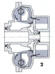
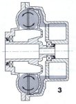
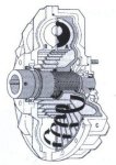
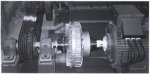
The Hydro-Flow hydrodynarnic coupling includes two basic elements: a pump A and a turbine B, which are both fitted with radial blades. Pump A is made of aluminium and is connected to the hollow shaft by splines. Ball bearings mounted on the hollow shaft are mounted in removable steel bearings, for easy maintenance. The turbine B is bolted to a half-case C. The mating face is sealed. The aluminium delay chamber R may be bolted to half-ease C. The mating face is also sealed. All the Hydro-Flow couplings are balanced dynamically and are all fitted with a fuse plug which releases the oil when the oil temperature exceeds +145C. Other protective devices may be provided on request. HO versions These versions are used as a baseline for all the other versions. HV versions This version includes a pulley whose cross-section and number of grooves are calculated to match the coupling power. HE and HC versions A SURE-flex or TEX-O-flex coupling flange is mounted on the coupling an allows the torque to be transmitted through a flexible element allowing misalignments. The replacement of the flexible element can be realized without misalignment of the shafts. The coupler can also be filled or drained with the driven machine loaded. HP versions A female PENCOflex hub is mounted on these versions in which the male hub engages. HT versions These are HATECO-type couplings which connect the coupling to the motor and the machine. Advantages Off-load start
Protection of the machine
Starting torque control Basic version: max. starting torque is lower than 200% of the nominal torque. With the delay chamber: the starting torque is lower than 150% of the nominal torque. Operating principles Basic model At startup, pump A which is integral with the motor forces the oil to move, under the centrifugal force. In steady state, the slight difference in speed of turbine B with respect to pump A sustains the oil motion, which produces a permanent load on the blades, owing to the oil’s kinetic energy. The torque is thus maintained permanently. Hence:
With a delay chamber
Effect on the electric motor When a squirrel-cage motor, mounted directly on a machine with a high inertia is started, a substantial current surge is generated for a long period. This period may be divided into two parts: the motors rotor startup period and the machine startup period. With an Hydro-flow coupling now fitted, the current absorbed by the motor during the machine startup phase is going to be reduced. With the Hydro-flow coupling, the motor can start as if there were no load. In this phase, the oil is not yet fully moving and the torque transmitted to the shaft of the driven machine is increasing slowly. This phenomenon is even more sensitive when a delay chamber is added. Thus the motor startup current IH or IR is reduced immediately. At motor speed nL, the machine starts when TH or TR > TL. The slipping of the coupling decreases gradually as the driven machines speed increases until the working speed nN is reached. For starting machines with high inertia, such as conveyor belts and fans, the Hydro-flow makes it possible to use motors of smaller sizes (reduced starting current and improvement of the power factor cosj). Then installing costly equipment becomes useless. Judicious selection of the oil filling level also makes it possible to influence the startup time.
Symbols t = time (S) Effect on the driven machine Curves TR and TH, for coupling with and without delay chamber, represent the torque transmitted to the driven machines shaft. The curves illustrate the favourable impact the Hydro-flow coupling has during startup. The maximum torque TH is much lower than the motors peak torque. In this case the Hydro-flow coupling really behaves as a torque limiter. Moreover, if the machine is jammed, the motors inertia is neutralized automatically. Depending on the oil level, and the selection of the Hydro-flow coupling, the starting torque may be between 1.2 and 1.5 times the nominal torque, with the delay chamber, and between 1.5 and 2 times without the chamber. When the machine is jammed, the maximum torque with or without the chamber is twice the nominal torque. Protective devices Hydraulic couplings, although different from torque limiters, are safety components capable of protecting the motor and the machine. Heating of hydraulic couplings directly which in turns depends on the transmitted torque. In case of continuous application of an excessive torque, the coupling’s temperature may exceed that tolerated by the oil, the seals and the bearings. To prevent this, fusible plugs should be installed. All installed, operation-ready couplings should be fitted with at least one fusible plug. There are two types of fusible plugs the standard fusible plug and the percussion fusible plug (see Fusible plugs). In addition to a standard fusible plug, or event an percussion fusible plug, an output speed controller can be installed (see Rotational speed controlled. This equipment monitors the coupling’s temperature by simply reading slippage. Important: for safety reasons, a protective case must be provided around the coupling. This must incorporate a drip tray with a capacity equal to or greater than that of the coupling. Drive from the outside Unless otherwise specified, the Hydro-flow hydrodynamic coupling is delivered for direct installation on the drive shaft (= normal arrangement). In certain cases, such as complete jamming of the machine or the need to control the coupling manually for filling purposes, it may be useful to reverse installation, i.e. for the coupler to be driven from the outside. This also allows more effective cooling in operation with repeated overload situations. Outer rotor B becomes the pump and inner rotor A becomes the turbine. As these two parts do not have identical blade shapes, this should be specified when ordering. Otherwise, the coupling will be delivered for normal arrangement and will not correctly fulfill its purpose as a start-up torque limiter. A coupling with pulley (HV and HVR) can be driven from the outside if the transmission ratio is 1:1 (call for details). Drive from the outside is prohibited on couplings with a brake disk or drum (H.D and H.B). For any request for a coupling driven from the outside, add “E” to the code (see Coding).
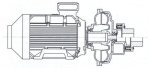
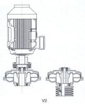
Vertical shafts General Under certain conditions, Hydro-flow hydrodynamic couplings can be installed in a position other than horizontal. Correct operation in the vertical position is only guaranteed if the pump is placed in the bottom position, whether drive is from the inside or the outside (see Drive from the outside).
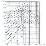
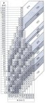
Motor at the bottom and drive from the outside: This position is not offered. Selection An Hydro-flow coupling may be selected in two different ways: Selection for IEC motors For each size of IEC motor, the table of the main catalogue section gives the size of the corresponding Hydro-Flow coupling according to the power to transmit and the applicable rotation speed. For the hollow shaft Hydro-flow couplings (with or without delay chamber) and for the corresponding versions with a delay chamber, the preferred bores Dl are recalled separately in the dimensional drawings and correspond to the diameters of the IEC motors’ shaft ends. The HV and HVR Hydro-flow couplings are indicated in the table shown on the dimensional drawing, with standard- groove pulleys selected according to the driving powers to transmit. Selection for other motors or according to the power required On the diagram below, the input speeds and the powers in kW are shown on the X and Y axes, respectively. The various areas give the field of application for the successive sizes of couplings shown in these areas. DO NOT USE SERVICE FACTOR. Note: in case of frequent startups or substantial overloads (more than 5 per hour), and for ambient temperatures higher than 40C or for an installation at more than 1000m over see, please consult us for checking the coupling thermal power.
Coding
Example
Hydro-flow coupling with PENCOflex coupling, with brake disc and delay chamber, size 620, disk diameter 795 mm, drive from the inside, shafts horizontal, bored hollow shaft to 100 mm, key with reduced height, bored coupling hub to 110 mm with standard keyway as per ISO R773, bore tolerance H7. Remarks: The hollow shaft is supplied bored with dimensions L1, LS and S here under:
Brake disk are made in steel and brake drums in cast iron GG 25. As from a 500 mm diameter, the brake drums are made of spherulitic graphite cast iron.
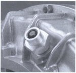
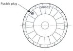
Fusible plugs Standard fusible plug Unless otherwise specified, this plug consists of a core made of a material which melts at a temperature of +145C. A different melting temperature can be supplied on request. The figure below defines the marking system of the plugs, according to melting temperature.
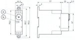
Note: A plug with a fuse temperature of 200C is possible but not recommended. When the oil temperature exceeds that of the plug, the fusible core melts and the oil is drained out of the coupling. Torque transmission is then stopped and the machine is no longer driven. The motor is no longer overloaded and undamaged. Important: for safety reasons, a protective case must be provided around the coupling. This must incorporate a drip tray with a capacity equal to or greater than that of the coupling. Percussion fusible plug This plug comprises a striker retained by a material melting at +120C. A temperature of +140C can be obtained on request. When the oil temperature exceeds that of the percussion fusible plug, the material melts and releases the striker. The striker then breaks a glass bulb which opens an electrical contact. This contact is available to the user to cut off the power supply to the motor and/or trigger an alarm, for example. (see Thermal protection below) This plug avoids draining the oil in case of excessive torque. Important: the percussion fuse plug should under no circumstances be installed without a standard fusible plug.
Thermal protection
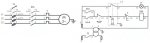
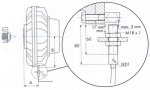
Example of wiring Coding D512-1: Electric contact IP66 with gland, base and glass fuse. Speed controller OPERATING PRINCIPLE As the transmitted torque is increased, this gives rise to an increased slip of the hydrodynamic coupling, and consequently, a decrease of the coupling case speed. It is therefore possible to detect this increase of the resisting torque (overload) of a Hydro-flow coupling driven from the inside, using an electronic rotational speed controller which measures its speed. A relay with change-over contact at the output may either emit an alarm signal or switch off the main motor. A delaying action of maximum 60 s prevents the unnecessary triggering of the relay, when the motor is started. It only occurs once when the operating voltage is applied. False alarms are prevented arising from I very short torque fluctuations, by the introduction of a preset time lag of 5 s.
Presetting Control adjustment – preset Accurate setting on the machine
Remarks
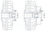
Example of wiring Coding D100: Speed controller Mounting Couplings in the as-delivered state The Hydro-flow couplings are delivered without oil. They are equipped with sealing rings capable of withstanding a continuous duty temperature of up to +90’C. For higher temperature, use special rings. Call for details. Mounting A protective cover encasing the coupling shall be provided to preclude any oil projections. The cover shall not impair cooling. The cover shall incorporate a drip tray with a capacity equal to or greater than that of the coupling. Case of the hollow shaft coupling mount the Hydro-flow coupling on the shaft using a threaded rod screwed in the shaft tapped hole, a spacing ring and a nut. To prevent the shaft from rotating, use a nut with a cheek-nut attached to the threaded rod, held by a second wrench. Remove the rod from the shaft and lock the coupling using a screw and a washer. When the coupling is installed on a motor shaft, use the motor’s inertia to unscrew the threaded rod and screw the axial attaching screw. For installation of the coupling parts of couplings types HE, HC, HP, HT, see the instructions relating to couplings SURE-flex, TEX-0-flex, PENCOflex and HATECO, respectively. Maintenance Maintenance of Hydro-flow couplings is limited to changing the oil every 8000 hours or once a year. As regards the coupling parts of couplings types HE, HC, HP and HT, see the instructions relating to couplings SURE-flex, TEX-0-flex, PENO0flex and HATECO, respectively. Disassembly Screw a threaded rod with a diameter as indicated in table below and extract the coupling. The threaded rod can be supplied on request.
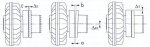
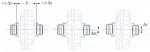
Alignment Align taking care to comply with the instructions of page 12 and the maximum Δ values below.
Filling Use an oil with a viscosity VG 1 5, VG22 or VG32 to standard ISO 3448. Remove the two fusible plugs acting as filling plugs and pour the oil quantity stated in the table below according to the coupling size. The letters in the table correspond to the coupling markings. Turn the coupling until the adequate marking is at the top point and fill the coupling until the oil reaches the filling port level. For optimum operation (minimum slip and start-up torque), determine the oil quantity as a function of the input power. The values not given in the table are calculated by interpolation. Increasing the oil quantity reduces slip but the peak torque to rated torque ratio will increase. The reverse occurs when reducing the oil quantity. A high slip reduces the coupler efficiency and increases the oil temperature. Refit the plugs. As these plugs have tapered threads, sealing is provided by tightening. A mounting compound can be used for easier installation.
|
|||||||||||||||||||||||||||||||||||||||||||||||||||||||||||||||||||||||||||||||||||||||||||||||||||||||||||||||||||||||||||||||||||||||||||||||||||||||||||||||||||||||||||||||||||||||||||||||||||||||||||||||||||||||||||||||||||||||||||||||||||||||||||||||||||||||||||||||||||||||||||||||||||||||||||||||||||||||||||||||||||||||||||||||||||||||||||||||||||||||||||||||||||||||||||||||||||||||||||||||||||||||||||||||||||||||||||||||||||||||||||||||||||||||||||||||||||||||||||||||||||||||||||||||||||||||||||||||||||||||||||||||||||||||||||||||||||||||||||||||||||||||||||||||||||||||||||||||||||||||||||||||||||||||||||||||||||||||||||||||||||||||||||||||||||||||||||||||||||||||||||||||||||||||||||||||||||||||||||||||||||||||||||||||||||||||||||||||||||||||||||||||||||||||||||||||||||||||||||||||||||||||||||||||||||||||||||||||||||||||||||||||||||||||||||||||||||||||||||||||||||||||||||||||||||||||||||||||||||||||||||||||||||||||||||||||||||||||||||||||||||||||||||||||||||||||||||||||||||||||

Established in 1992, Mecco represents a number of power transmission companies from Switzerland, Germany, Austria, USA and Italy.